
What is PICkit 3 Programmer?
PICkit 3 programmer/debugger is a simple, low-cost in-circuit debugger that is controlled by a PC running MPLAB IDE (v8.20 or greater) software on a Windows® platform. The PICkit 3 programmer/debugger is an integral part of the development engineer’s toolsuite. The application usage can vary from software development to hardware integration.
The PICkit 3 programmer/debugger is a debugger system used for hardware and software development of Microchip PIC® microcontrollers (MCUs) and dsPIC® Digital Signal Controllers (DSCs) that are based on In-Circuit Serial Programming™ (ICSP™) and Enhanced In-Circuit Serial Programming 2-wire serial interfaces. In addition to debugger functions, the PICkit 3 programmer/debugger system also may be used as a development programmer. The PICkit 3 programmer/debugger is not intended to be used as a production programmer.
PICkit 3 Programmer Features:
USB (Full speed 12 Mbits/s interface to host PC)
Real-time execution
MPLAB IDE compatible (free copy included)
Built-in over-voltage/short circuit monitor
Firmware upgradeable from PC/web download
Totally enclosed
Read/write program and data memory of microcontroller
Erase of program memory space with verification
Program up to 512K byte flash with the Programmer-to-Go*
Diagnostic LEDs (power, busy, error)
Supports low voltage to 2.0 volts (2.0v to 6.0v range)
Freeze-peripherals at breakpoint
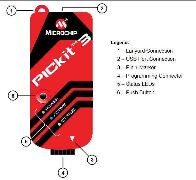
Header Information
PICkit 3 Programmer Functions:
Debug your application on your own hardware in real time
Debug with hardware breakpoints
Set breakpoints based on internal events
Monitor internal file registers
Emulate at full speed
Program your device
PICkit 3 Programmer Software Download
MPLAB X IDE Windows,Linux,OSX,please download here
PICkit3 Programmer Application v3.10 Download
How to Install USB driver for PICkit 3 Programmer?
The PICkit 3 uses generic USB drivers that are installed automatically. You do not need to do anything.
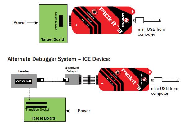
How to Connect Target & Power for PICkit 3 Programmer?
1.Attach the PICkit 3 to the computer using the USB cable.
2.Attach the communications cable between the debugger and target board.
3.Connect power to the target board.
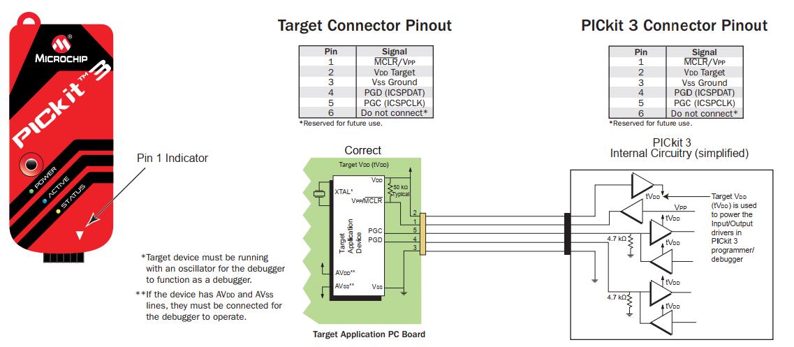
PICkit 3 Programmer Circuitry and Connector Pinouts
PICkit 3 Programmer Recommend Component Settings:
| Oscillator | • OSC bits set properly • Running Supplied by target |
| Power | |
| WDT Code-Protect |
Disabled (device dependent) Disabled |
| Table Read Protect Disabled | |
| LVP BOD JTAG |
Disabled VDD > BOD VDD min Disabled |
| AVDD and AVSS PGCx/PGDx |
Must be connected Proper channel selected, if applicable |
| Programming | VDD voltage levels meet programming specs |
PICkit 3 Programmer Target Circuit Design Precautions:
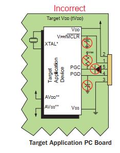
- Do not use greater than 100 µF capacitance on VDD: dependingon the overall load, it will prevent the target from powering quicklywhen PICkit 3 is the source of power.
• Do not use capacitors on MCLR: they will prevent fast transitions of VPP.
• Do not use pull-ups on PGC/PGD: they will divide the voltage levels since these lines have 4.7 kΩ pull-down resistors in PICkit 3.
• Do not use multiplexing on PGC/PGD: they are dedicated for communications to PICkit 3.
• Do not use capacitors on PGC/PGD: they will prevent fast transitions on data and clock lines during programming and debug communications.
• Do not use diodes on PGC/PGD: they will prevent bidirectional communication between PICkit 3 and the target PIC®MCU.
• Do not exceed recommended cable lengths: refer to the Hardware Specification section of the PICkit 3 online help or user’s guide for acceptable cable lengths.